
Principles of Frequency Withstand Test Equipment
In the realm of high voltage transformer testing, understanding the working principles of Frequency Withstand Test Equipment is crucial. This equipment is typically a single-phase transformer with connection group I. I. Utilizing a frequency of 220V (or 380V for capacities above 10kVA), the power supply is connected to the ∕XC∕TC series control box (or console). The voltage is then adjusted through an autotransformer (external for capacities above 50kVA) within the control box to output a voltage of 0-200V (or 0-400V) to the primary winding of the Frequency Withstand Test Device.
Electromagnetic Induction: The Key Mechanism
The principle of electromagnetic induction is fundamental here. By applying voltage to the primary winding of the Frequency Withstand Test Device, a high voltage required for testing is induced in the high voltage winding.
1. Single High Voltage Tester Working Principle: Refer to illustration 3 for a schematic representation of a single high voltage tester’s working principle.
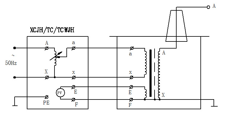
Figure 3: Schematic diagram of a single power frequency withstand voltage test device
2. Single Frequency Withstand Test Device: As shown in illustration 4, the high voltage bushing contains a high voltage silicon stack in series with the high voltage circuit for half-wave rectification to obtain a direct current high voltage. When a short-circuiting rod shorts the silicon stack, an alternating current high voltage is obtained as the output; removing the rod switches to direct current output.
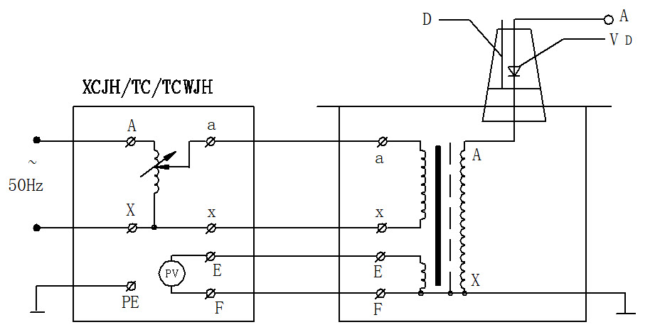
Figure 4: Schematic diagram of a single power frequency withstand voltage test device
In the picture: D – short circuit bar VD – high voltage silicon stack
3. Series Connection for Higher Voltages: Illustration 5 demonstrates how connecting three Frequency Withstand Test Devices in series can achieve higher voltages. This series connection offers significant advantages. Each individual Frequency Withstand Test Device is compact, low voltage, and lightweight, facilitating easy transport and installation. These can be connected in series to multiply the output voltage of a single device or used separately in multiple sets. This modular approach is cost-effective and offers flexibility. In illustration 5, each unit in the first and second stages contains an excitation winding A1, C1, and A2, C2, respectively. The low voltage power supply is connected to the primary winding a1x1 of the Frequency Withstand Test Device I, and each of the test transformers I, II, III outputs a voltage V. The excitation windings A1, C1 power the primary winding of the second-stage Device II, and the windings A2, C2 power the primary winding of the third-stage Device III. The bodies of Devices II and III are insulated from the ground and are at high potentials of 1V and 2V, respectively, while the Device I is grounded. Thus, the rated output voltages of the first, second, and third stages relative to the ground are 1V, 2V, and 3V, with rated capacities of 3P, 2P, and 1P, respectively.
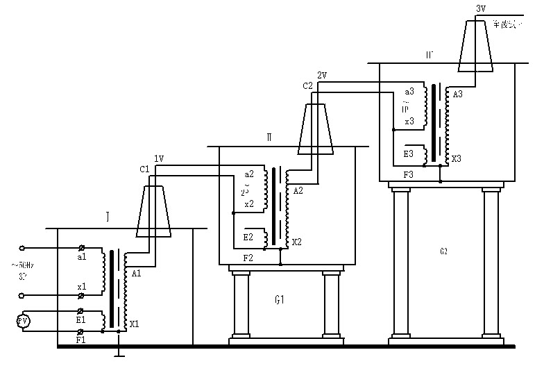
Figure 5: Schematic diagram of cascade wiring of three power frequency withstand voltage test devices
In the figure: P – Capacity (kVA) V – Voltage (kV) G1, G1 – Insulation bracket
The high-voltage silicon stack in the high-voltage bushing of the power frequency withstand voltage test device is not shown, but its principle is the same as the above figure.
Mastery Through Understanding
In my years of experience in power system testing, the importance of understanding the operational principles of test equipment cannot be overstated. It ensures not only the effectiveness of the tests but also the safety and reliability of the power systems we work to maintain.
