YuanYuanXin Industrial Park

China, Wuhan 430040

+86 136 572 20727

24/7 Customer Support

Email:cici@sansionpower.com

Online for your needs on test solution

AC Resonant Test System

Optimizes testing for capacitive load applications.

PRODUCTS CATEGORIES

Previous slide
Next slide

Customized needs

Phone:+86 136 572 20727       Email:cici@sansionpower.com

AC Resonant Test Systems are particularly beneficial in scenarios where the load is predominantly capacitive with minimal loss. This includes applications such as testing power cables, gas-insulated switchgear, capacitors, generator windings, and dry testing of insulators. These systems provide an efficient and reliable solution for assessing the dielectric strength of these components, ensuring their safe and effective operation.

The principle of the AC Resonant Test

In the AC Resonant Test, resonance is achieved when XL=XC, where XL=2πfL(inductive reactance) and XC=1/2πfC(capacitive reactance). At resonance, the power supply mainly covers the losses and resistive parts, significantly reducing the total power needed for high voltage testing.

Main Components of The Systems

HV Divider

Measures peak high and low voltages on regulators, ensuring safe, transparent testing and production.

HV Reactor

Enhances voltage waveform in resonance devices, boosts system power factor, and is essential for resonating with capacitive test items.

Excitation Transformer

Boosts voltage from variable frequency power supply and isolates high from low voltage.

Frequency Power

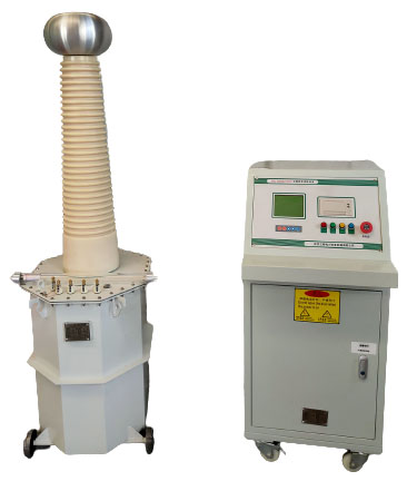
Transforms 220V/380V, 50Hz power into adjustable frequency and voltage, combining operation, protection, control, and monitoring in one unit.

Testing Applications:

  • AC withstand tests on cables and cable samples
  • Applied voltage tests on transformers
  • AC withstand tests on GIS, capacitors, generators, and motors
  • HV tests on voltage and current transformers

Benefits

  1. AC Resonant Test Systems require minimal power as they only need to cover the losses in the test circuit, enhancing energy efficiency.
  2. The test power and voltage can be customized to meet specific needs, and can be amplified through parallel and series connections of reactors.
  3. These systems generate a less distorted high-voltage sinusoidal output compared to a standard AC Dielectric Test System with similar ratings, ensuring more accurate results.
  4. They only require low, single-phase input power, leading to reduced installation and operational costs, making them a cost-effective solution for dielectric testing.

AC Withstand Voltage Test System Wiring

Variable Frequency Series Resonance Test Wiring Diagram for Power Cables

Variable Frequency Series Resonance AC Withstand Voltage Test Wiring Diagram for Transformers and GIS

Specification

  • Rated Capacity: 300KVA – 20000KVA
  • Rated Voltage: 200KV – 2000KV
  • Rated Current(HV): 1A-100A
  • Working Power: 380V 50Hz/60Hz
  • Quality Factor: Q≥50
  • Load Cycle and temperature rise: 1 hour of rated operation, the temperature rise of the device coil ≤65K
  • Noise ≤65dB
  • Output Frequency: 20-300Hz
  • Output Voltage Wave: sinusoidal waveform, the waveform distortion rate ≤1%
  • Frequency Adjustment Sensitivity 0.1Hz, Instability≤0.05%

Model

Input Voltage(V)

Output Voltage(kV)

Capacity(kVA)

Scope of application

Main configuration

SXBP

108/108

220

0-108

108

1.31500kVA/35kV power transformer

2.35kVA circuit breaker, closed bus, insulator

3.10kV (300㎡) cable 2km

4.35kV (300㎡) cable 0.5km

A.1 set 10kW transformer

B.1 set 10kVA excitation transformer

C.4 sets of 27kV/1A reactor

D.1 set 120kV voltage divider

SXBP

216/216

220

0-216

216

1.110kV circuit breaker and bus

2.110kVA GIS≤10 partition

3.35kV (300㎡) cable 1.5km

4.10kV (300㎡) cable 3km

5.110kV fully insulated main transformer

A.1 set 10kW transformer

B.1 set 10kVA excitation transformer

C.4 sets of 54kV/1A reactor

D.1 set 250kV voltage divider

SXBP

270/270

220/380

0-270

270

1.110kV GIS switch and power transformer

2.10kV (300㎡) cable 5km

3.35kV (300㎡) cable 2km

A.1 set 20kW transformer

B.1 set 15kVA excitation transformer

C.5 sets of 54kV/1A reactor

D.1 set 300kV voltage divider

AC Resonant Test System usage examples and calculations

Test 35kV/300mm2 cable 1km, working time 1 hour, test voltage 52kV.

Check the table to find that the capacitance is 0.19uF. Check our reactor nameplate to find out: the voltage is 27kV, the current is 2A, the inductance is 54H, and the working time is 1 hour.


Because the test voltage is 52kV and the single-section reactor is 27kV, two reactors need to be connected in series with a voltage of 54kV. When connected in series, the sum of the inductances is 108H;


The frequency calculation formula is f=1/(2π√LC), substitute it into the formula, the calculated frequency is 35.1Hz, the current calculation formula is I=2π*f*U*C, substitute it into the current calculation formula, the calculated current is 2.17A, which exceeds the reactance The rated current of the device is 2A. It is necessary to change the reactor configuration to 2 series and 2 parallel. The inductance characteristics are addition when connected in series and division when connected in parallel. The inductance is (54×2)÷2=54H. Mutual inductance can be ignored. The current addition is 2+2=4A, then substitute it into the frequency calculation formula, the frequency is 49.68, substitute it into the current formula, the calculated current is 3.08A.


Therefore, the current meets the requirements, the voltage of 54kV also meets the requirements, and the frequency of 49.68 is between (30-300Hz), which also meets the requirements. This configuration can meet the requirements of the product under test.

AC Resonant Test System configuration, wiring and precautions

According to calculations, the configuration is: 1 pc power supply, 1 pc excitation transformer, 4 pcs of 54/27 reactors, 1 pc voltage divider above 60kV, and 1 set of accessories (including power cords, grounding wires, discharge rods, etc.).

Precautions:

1. Measure the insulation resistance before the test, and only the insulation resistance can withstand voltage if it passes the test;


2. Power supply line: the voltage must be stable, the wire diameter must be sufficient when transmitting power over long distances, and 220V and 380V must be distinguished;


3. The grounding of the voltage divider connecting wire is particularly important: it must be connected to a reliable grounding point. If there is any rust, it must be polished. If possible, it is best to measure the resistance value to be less than 0.5Ω. Pay attention to water pipes, street lamps, and iron frames. The depth of the ground pillar must be deep enough;


4. The high-voltage leads should be kept as short, straight and suspended in the air;


5. The reactor must be placed on a dry ground and covered with a sufficiently high insulating board (standard: single-section reactor voltage 1kV/mm). Do not place it on mud floors or iron plates, or on cars. When the insulating bottom plate is higher than 3 times the voltage of the single-section reactor;

6. Reactors are connected in series/parallel. The series connection is one on top of the other and cannot be laid flat.

Principles for using excitation transformers

Look at the label to determine how many sets of voltage outputs there are:
1. The output voltage of the excitation transformer is ×30 times the high voltage that can be output. When used as a generator, it can only be ×8 times.


For example: when the output voltage is 3kV, the high voltage can reach 90kV.


2. The current is greater than or equal to the current of the reactor.
For example: at 6kVA/3kV output, it can provide a maximum current of 2A.


3. When the excitation transformers are connected in series/parallel, the series connection provides high voltage, and the parallel connection increases the large current.

Related Products